The Exhaust Valve (EXUP®) cables control the valve which varies exhaust back pressure. This allows greater power throughout the rpm range. Too loose cables can impair the proper operation of the valve. Too tight cables can prevent the servo motor from operating.
Bob K. (eskort) from the Owners Association packaged this writeup as a Microsoft Word® format document suitable for printing. You may download that here.
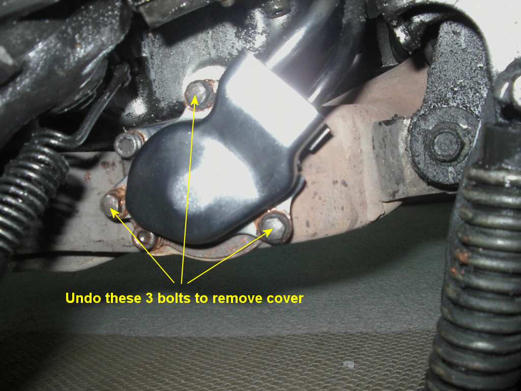
Remove the Exhaust valve pulley cover. This is located on the left side of the bike down low just in front of the centerstand. Remove the bottom and left bolts with an 8mm socket head, the top bolt just needs to be loosened. The cover then slips off.
 |
| 1600 x 1200 |
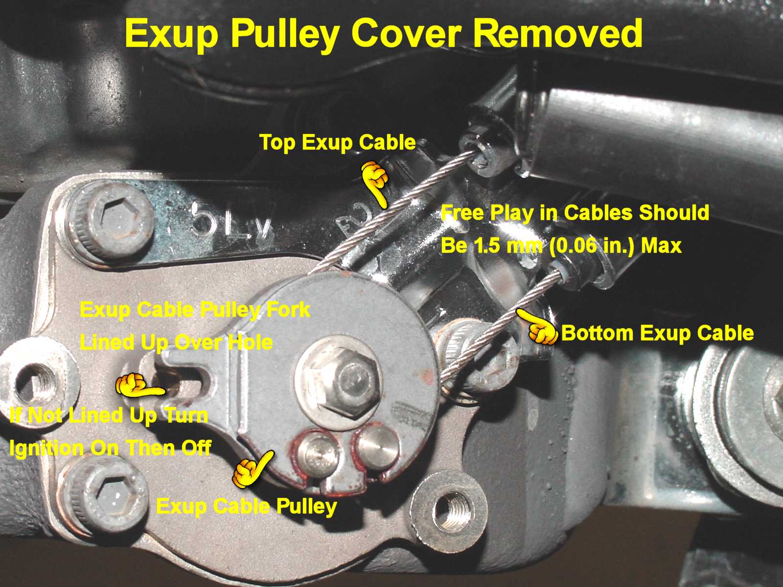
Underneath the cover is the Exhaust Valve pulley. It is controlled by two cables. The free play in each cable should not exceed 1.5 mm (0.06 in.). That 1.5 mm is free slack, movement without any pressure at all, not as far as you can push it. Mine were very loose. The 'fork' in the pulley should line up over the hole as shown. If it does not then it may be 30 degrees or more advanced. Turn the ignition ON then OFF. The pulley fork should now be aligned over the hole.
If the pulley is not lined up over the hole then the cables are very likely improperly adjusted beyond the tension adjustment. You should loosen both cables until you can manually rotate the pulley until it lines up over the hole (see below how to loosen the cables.) You should do the ignition ON then OFF sequence again to make sure the servo motor is properly zeroed. Then proceed with the tension adjustment.
 |
| 1600 x 1200 |
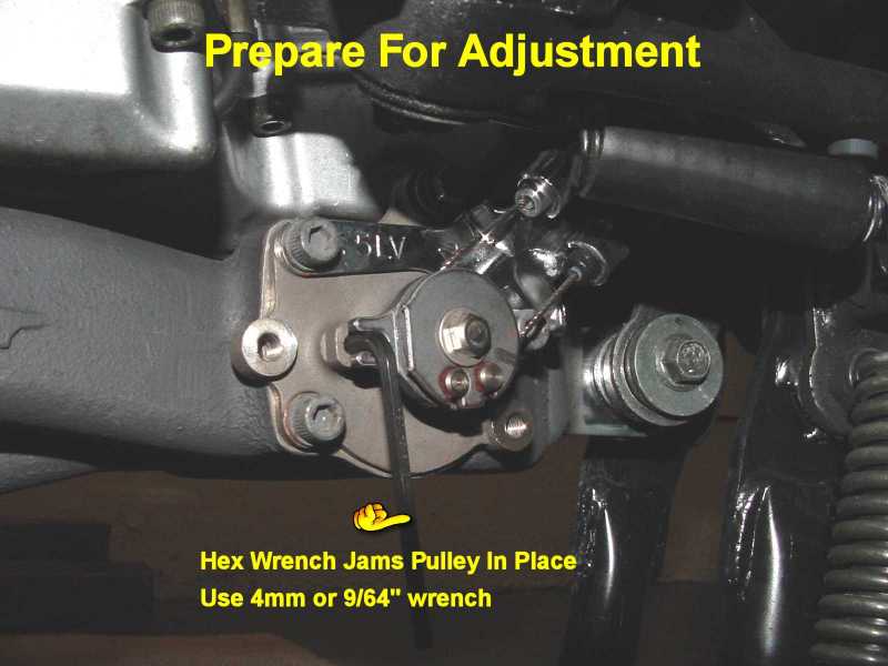
Prepare the pulley for cable adjustment by jamming the pulley in place. Use a 4 mm or 9/64 in. hex wrench as shown. For me 4 mm was a bit too big, 9/64 in. was just right.
 |
| 1600 x 1200 |
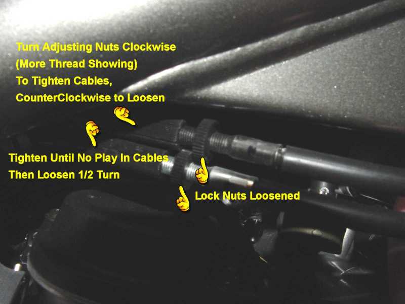
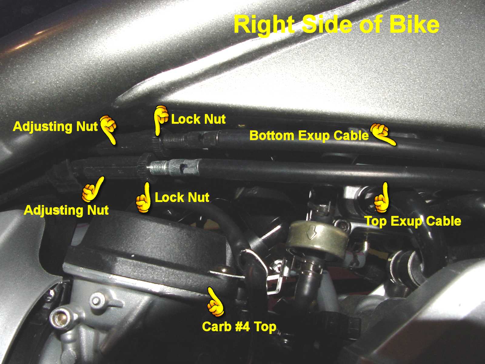
On the other (right) side of the bike just under the tank and above the carb top are the two Exhaust Valve cables with adjusting nuts. Loosen the lock nuts. Tighten the cables up to the point where there is no free play at all. Turn the adjusting nuts clockwise (more thread showing) to tighten the cables, counterclockwise (less thread showing) to loosen. The service manual contradicts this direction but that's just a matter of which side of the nuts you are looking from. The important thing is the amount of thread showing. On my bike, the cable with the silver colored threads was for the top cable as seen on the pulley, the cable with the black threads was for the bottom cable as seen on the pulley. I was able to actually feel when the cables had no more play as I turned the adjusting nuts one way then the other. The resistance to turning the adjustment nut increases a lot at the very point where all the slack is taken up. Lastly, loosen each adjusting nut one-half turn. This should produce just the right amount of free play. Verify this by checking the cables on the pulley.
 |
 |
| 1600 x 1200 | 1600 x 1200 |
Tighten the lock nuts.
Replace the Exhaust Valve valve pulley cover (10Nm, 7.2 lb-ft) (I just tightened the bolts until snug).
Next time you start the bike, make sure you don't get the 7000 rpm error code on the tach. If you do, it likely means that the servo motor is unable to actuate the exhaust valve because the cables are too tight. The bike can be ridden like this because the electronics will cut off power to the servo motor so it doesn't burn out. Loosening the cables should make that error code go away.
EXUP® Valve Maintenance:
From Mike Greatorex, a regular contributor to the FZ1OA forum, comes this procedure for maintaining the EXUP® valve.
The Exhaust Ultimate Power Valve (EXUP®) alters the back pressure in the exhaust system at various revs.
It consists of a gate valve in the EXUP housing, the cast exhaust section immediately behind the headers and
below the engine. The valve is operated via cables driven by a servo motor located towards the front left of
the engine beneath the fuel tank.
The valve should start to open from its closed position at 2000 rpm and be fully open by around 6000 rpm.
At lower revs the valve restricts the exhaust gas flow improving the scavenging of the motor and increasing torque.
Above 6000 rpm, the valve is completely clear of the gas flow and the system performs like any other non-EXUP® equipped exhaust.
Proper functioning of the valve is important to engine performance but, inexplicably, maintenance of the valve does
not feature in Yamaha’s routine maintenance schedule.
The Haynes® manual for the early model R1's (which have an identical EXUP® system) recommends checking cable
adjustment every service (4k or 6k depending on model year) and says that the valve should be stripped and cleaned
‘regularly’, due to it being located in an area vulnerable to dirt and corrosion.
Problems with the valve operation are indicated by a 7k rpm fault code on the tacho. Usually this means that the
cables are too tight, causing the servo motor to bind, or that the valve itself is sticking or has seized in its
housing. Occasionally, the problem may be with the servo motor itself, but this is rare.
The valve is assembled dry at the factory and corrosive elements in the exhaust gases can cause it to stick quite
early in the machine's life. Bikes left to stand unridden for a while may show the 7k rpm fault code on start up,
but the valve later releases due to heat and vibration. This is due to corrosion nipping the valve up in its bushes
and is a sure sign that the EXUP should be stripped and greased.
Because EXUP® maintenance doesn't feature in the service schedule, it often gets overlooked by dealers. Apart
from increased cable slack adversely affecting engine performance, another downside of neglect is that the cover
and end plate bolts can seize in place.
Personally, I stripped and copper greased all the EXUP® components as soon as I took delivery of my new R1 and
latterly, my new Fazer 1000. I've accumulated close to 40k miles on both bikes and have never had a problem with the EXUP®.
Conversely, I've worked on many Fazer 1000's with upwards of 10k miles on the clock and it was obvious that the valve had
not been touched from new. Removing some of the cover and end plate bolts was a nightmare, and the cable freeplay
was invariably way out of specification.
Dismantling, cleaning and re-assembling the EXUP® is a simple job and only requires a few tools:
The valve is easily accessible and the job should take no more than 1 hour for a first-timer.
Here's how you do it:
See Photo 1 below. Remove EXUP® cover. If the bolts are stiff and reluctant to move, take care. If they've not
been removed from new and have corroded in place, it's easy to shear the heads off the bolts. Use heat, plenty of
penetrating fluid and loads of patience. Drilling out a sheared off bolt is a real pain!
See Photo 2 below. Remove the pulley. Hold the pulley in place by putting a punch or suitable sized rod through the
pulley forks into the hole in the EXUP® end plate. Undo the 8mm bolt and remove the bolt and washer.
Note the orientation of the pulley on the spindle before removing it. Be ready to catch the spring and large flat washer
immediately behind the pulley.
Note how the cables fit into the pulley (mark them if necessary) and remove the pulley from the cables. You can leave
the cables in the pulley and just push them to one side, but it's not a bad idea to dismantle, clean and lubricate all
EXUP® components during maintenance.
See Photo 3 below. Undo the 3 x 5mm allen bolts holding the EXUP® housing end plate. Move the cable holder and
cables to the side and pull the end plate off the valve housing.
These bolts may also be corroded, so go at them cautiously.
If the end plate is stuck, a light tap around the joint should free it. Don’t try to pry it off or get heavy-handed
with it, as it is a bronze alloy casting and could crack.
The valve will probably come out attached to the end plate and it should also have a 3mm spacer on the opposite end.
Exceptionally, the bronze bush from the far end of the housing may also come out on the valve spindle.
See Photo 4 below. Once all the components are removed from the machine, clean them thoroughly and lay them out for
inspection and reassembly as shown below.
I have found that the valve is inclined to stick in the end plate housing bush, meaning that the bush is rotating in
the housing rather than the valve rotating in the bush.
If this occurs, to release the valve from the bush, drift it out gently by tapping on the end of the spindle. Support
the end plate casting while doing this and be careful not to let the valve drop onto the floor when it releases.
I'm not a metallurgist, but a lot of the EXUP® components look like bronze alloy and may be susceptible to cracking.
I know for a fact that they’re expensive, so take care!
Clean up the valve spindle ends with wire wool or emery paper and then check that they fit and turn easily in the bushes.
Apply a generous coat of copper grease to the spindles and bushes. Note that Haynes® and Yamaha® manuals both
state that copper grease is fine for this application. You can use more exotic, higher melting point grease if you
wish, but it's not necessary.
See Photo 5 below. Refit the valve into the end plate bush. Note that there are two stops cast into the inner side of
the end plate. Make sure the valve is correctly located relative to the end stops.
Ensure the 3mm spacer is fitted to the spindle as shown, and also the far end bush if this came out with the valve.
Refit the valve into the valve housing locating the spindle in the bush shown in Photo 6 below.
Refit the end plate bolts with the cable holder in the correct position. Apply a generous coat of copper grease to the
allen bolts beforehand. Tighten the bolts to the correct torque.
All the bolts in the EXUP® system should be torqued to 10Nm.
If you don't have a torque wrench, hold the socket or ring spanner with your hand directly next to the bolt head and
tighten it with just your wrist strength. Don't lean into it like you’re arm wrestling.
Check that the valve rotates freely in a clockwise direction until it hits the end stops. It will usually fall back to
the closed position when released.
If the valve is binding, slacken the cover bolts slightly and check again. If the valve now rotates freely, remove the
end plate and look for the cause of the binding.
Place the large washer and then the spring (narrow end outwards) on the valve spindle, then refit the pulley and cables,
referring back to the previous photos to confirm correct orientation.
Ensure that all bolts are given a coat of copper grease on reassembly, likewise the cable nipples.
Before finally replacing the EXUP® cover, check and set the cable freeplay following the instructions starting at the
top of this web page.
Once you have done this job for the first time, you’ll understand how easy it is to keep the EXUP® clean and correctly adjusted.
I recommend you include a full dismantle and lube as well as a proper cable adjustment in every 6k miles service.
Last Updated: 03-07-2008
Copyright © 2001-08, Patrick Glenn, All Rights Reserved.
The information presented here reflects solely my personal experience with my motorcycle and is presented
for entertainment purposes only. No information presented here is to be relied upon for issues of rider safety
nor to replace the services of a qualified service technician.
Any attempts to follow or duplicate any of these procedures are done so completely at your own risk.
By reading the information on this site, you agree to assume complete responsibility for any and all actual
or consequential damages that may arise from any information presented herein.


Back to Pat's Motorcycle Page
Yamaha®, FZ1®, and EXUP® are registered trademarks of the Yamaha Motor Corporation.
This site is not affiliated in any way with the Yamaha Motor Corporation.