I decided to go ahead and try the Factory Billet Aluminum Lower Bar Mounts (Part # ABA-5LV91-60). These lower the bars by about an inch.
I kept the rotated orientation described above so that the lowering would be additional.
They were ordered from Arizona Motorsports. The retail
price from Factory dealers is $84.95. AZ lists them for $76.45. The additional 10% Owners Association discount lowers this to $67.96. Shipping is
$9.95 for a total of $77.91.
The first step is to remove the stock mount. Make sure the bike is level and on the centerstand.
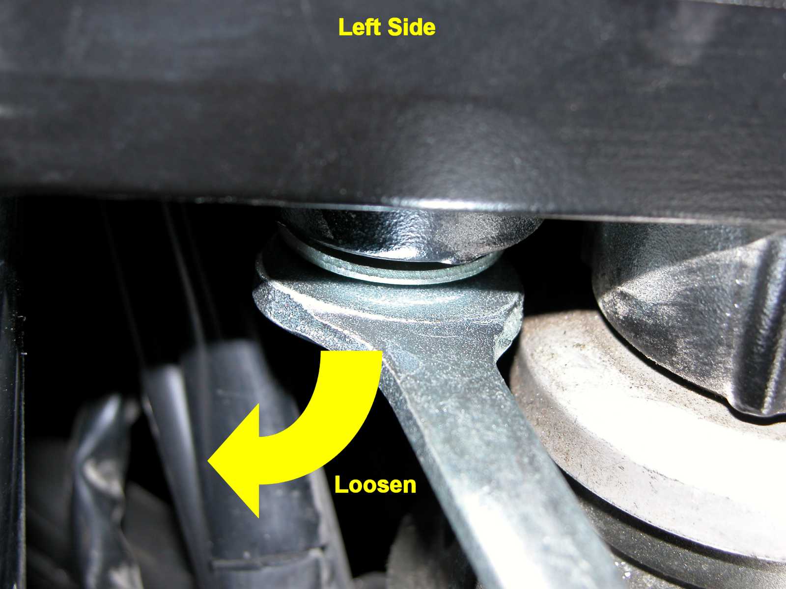
Start by loosening the two 14 mm lock nuts underneath. There is no room
for a socket wrench so use the 14 mm wrench supplied with the Factory tool kit. Turn the wheel one way then the other
to make more room. You can also raise the tank to make a bit more room for the wrench. The lock nut is stiff to turn
so leave the top of the mount in place to make the nut removal easier. Unscrew these nuts most of the way off.
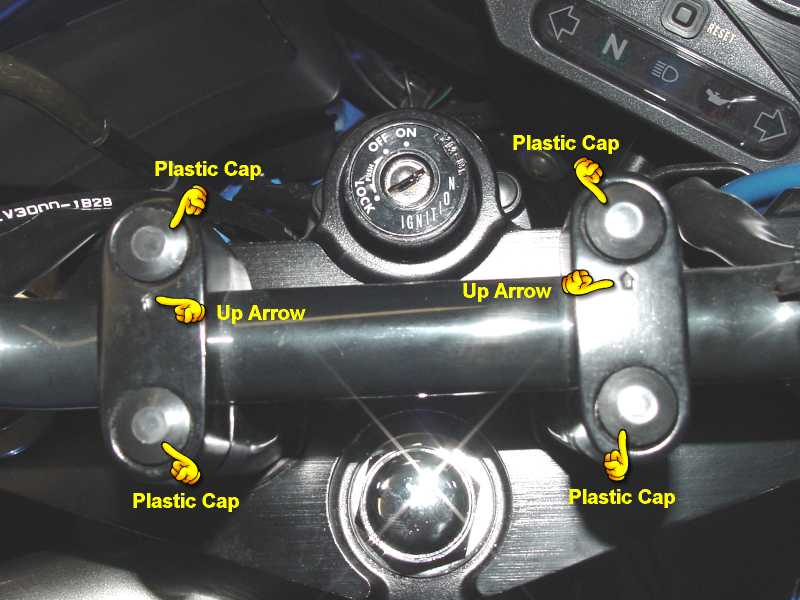
Next, remove the top mounts. Remove the plastic Allen bolt caps with your fingernails. Be careful not to lose them.
Use a 6mm Allen wrench on the hold down bolts. Loosen the rear two (closest to the rider) first then the front two.
Lift off the top of the mounts then carefully lift the bars up and move them up and out of the way. Save the Allen bolts
for reuse when installing the lower mounts.
Finish removing the two lower lock nuts underneath and remove the lower portion of the stock mounts. Save the lock
nuts as well as the large lower washer and small upper washer for reuse.
Try not to lose or drop the washers. I dropped one of the small upper washers and it disappeared underneath
the tank. After a long, frustrating search on my knees with a flashlight I finally found it in the spark plug
recess hole for cylinder #1. Ugh!
These pictures show the comparison between the stock and lower mounts.
Install the lower portion of the new mounts. The orientation should be such that the mount completely
covers the rubber insulator in the triple clamp. Replace the small washer first in the recess on top and don't
forget the large washer underneath. Watch the orientation of the lock nut which will be stiff to screw in.
Screw the lock nuts most of the way but don't tighten yet so you can still adjust the position of the mount.
Repositioning the bars is the toughest part. There are two degrees of freedom. Left/Right centering and
rotation. It's difficult to make sure they are centered because you can't see the bars when you place the
top of the mount over the bars. I just did the best I could with centering then holding the bars in place
and finger tightening the Allen bolts. The rotation of the bars should be such that the top of the brake
master cylinder is level. Make sure that the bars do not contact the tank at full right and left lock.
I ended up with a tight clearance. Rotating the bars upwards would increase the clearance but I wanted them
at that angle.
An idea sent to me from owner Bill Hines is to first mark the handle bar position while it is properly
centered on the stock mounts with painters masking tape. This makes replacing the bars on the bew lower
mounts much easier and ensures that they remain centered.
Tighten the bolts on the top to spec (17 lb-ft, 23 Nm). The top piece of the mount is designed so that
there should be a gap facing rearward. That is why you tighten the top (forwardmost) bolts first then
the bottom (rearwardmost) bolts second. Finish tightening the bottom bolts (23 lb-ft, 32 Nm). I couldn't get a torque
wrench in there for the bottom bolts so I just tightened them as much as I could using that rather
short wrench provided with the tool kit. Replace the plastic caps over the top Allen bolts.
Make sure the throttle and clutch cables do not bind excessively at full right and left lock. My throttle cable is
a bit sluggish at full lock but does return quickly to full closed position. At center position it snaps
back instantly.
Here is a comparison image of the bars before and after.
The riding position is noticeably altered being more aggressive and forward leaning. There is much more
an impression of being over the bars with the improved road feel that provides. I was afraid the position
would be too uncomfortable for my bad back and recently weakened wrist but that was not the case. It is
incrementally tougher on the back and wrists but not excessively so. For everyday sport riding or commuting
it is recommended. For touring on long rides I would prefer the greater comfort of the stock mounts however.
Addendum:
From Mark Hunter:
I used another approach. Instead of just rotating the bars a little towards the rider, I stripped them completely.
I removed the grips, loosened the levers, took off the ignition assembly, and anything else attached to the bars and then hung them
around the cowl. I then completely removed the bars, flipped them 180 degrees right side to left and then rotated
them away from the rider, all the way around till they touched the fork bolts. I then put all the stuff back on. The
result is a riding position more like an R1. The only drawback is that the bars end up just shy of full lock left unless
I can figure out a way to move the cluster deeper into the fairing.
Last Updated: 02-19-2003
Copyright © 2001-03, Patrick Glenn, All Rights Reserved.
Yamaha® and FZ1® are registered trademarks of the Yamaha Motor Corporation.
This site is not affiliated in any way with the Yamaha Motor Corporation.
The information presented here reflects solely my personal experience with my motorcycle and is presented
for entertainment purposes only. No information presented here is to be relied upon for issues of rider safety
nor to replace the services of a qualified service technician.
Any attempts to follow or duplicate any of these procedures are done so completely at your own risk.
By reading the information on this site, you agree to assume complete responsibility for any and all actual
or consequential damages that may arise from any information presented herein.


